No Nc Relay Wiring Diagram
The no (normally open) connection of the relay is not connected until the relay turns on. The coil circuit’s terminals are 85 and 86.
China 60A NO NC Latching Relay Manufacturers and Suppliers

Following grating to remove, replace or fix the wiring in an automobile, having an accurate and detailed no nc relay wiring diagram is.

No nc relay wiring diagram. Mengenal cara kerja magnetic contactor kontaktor pengunci dan terminal no nc listrik diagram kerja. This diagram shows it more clearly as a single unit. The below figure illustrates an example of a simple ladder program with the no and nc contacts driving an output rung.
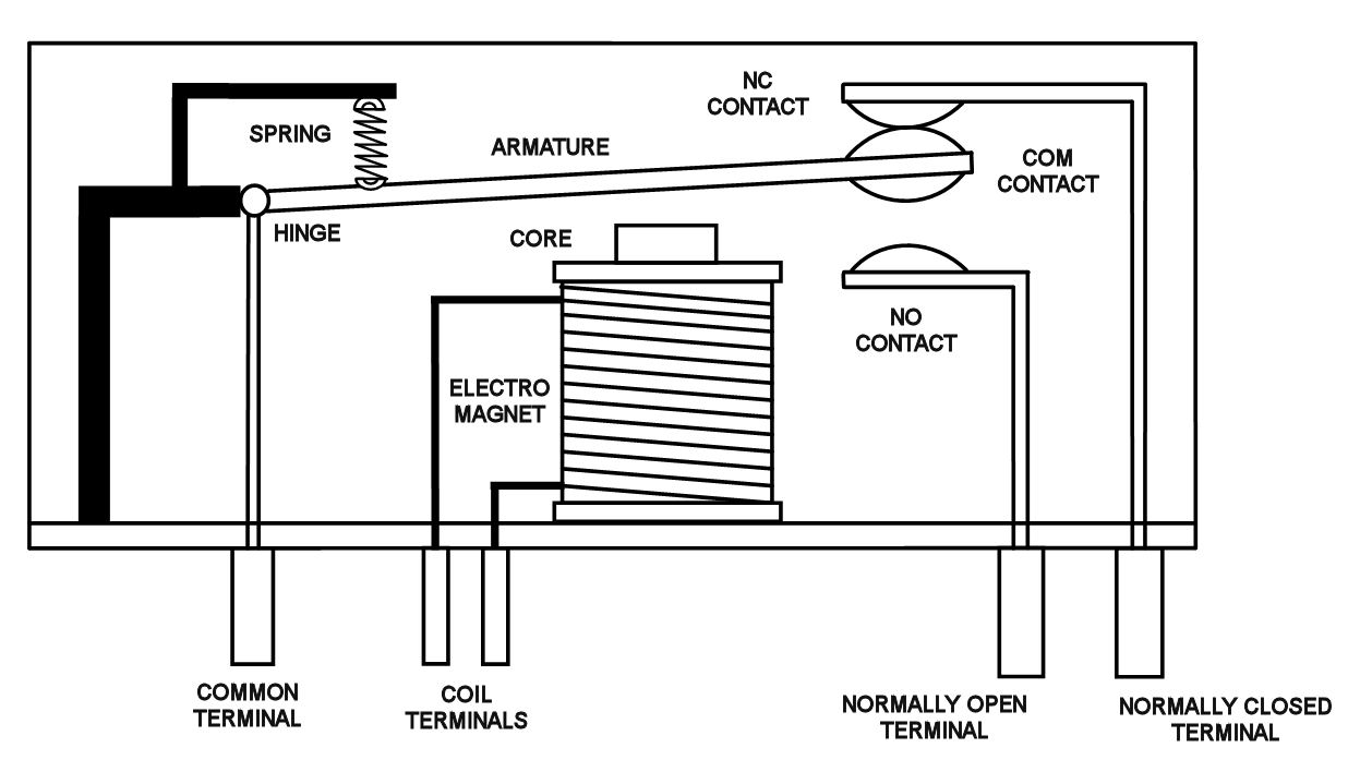
This magnetomotive force helps the spring to move the armature body of no and nc contact. Connect one end of the first wire to the first low current terminal on the solenoid switch. The nc contact of a limit switch, when used in a circuit breaks the circuit or current flow when its actuator is pressed.
A relay is a switch that connects and disconnect electrical or electronic circuits according to the electrical signals applied to it. A relay has two circuits, a coil, and high amperage circuit. 3/0) contacts and the pilot light pl1 will be lit.
Relay can be the best option to control electrical devices automatically. There are different types of relay available. As internal parts, it has a magnetic coil, movable open contact mechanism and closed contact mechanism.
This supply voltage in series with the load may be as per the load specifications. Each circuit has two terminals. Now see the attached wiring diagram of a typical 3 button station.
‘’welcome’’ friends how to do ease learning electrical and electronic to join our channel ,subscribe my channel and thanks for watching video”.relays allow. A wiring diagram is a simplified traditional photographic representation of an electric circuit. The red led now shuts off and the green led turns on.
The no terminal of the relay gets power only when the relay is powered. Angelo on september 5, 2021. This is the most common type used in the access control industry.
The other side has three low voltage pins (ground, vcc, and signal) which connect to the arduino. No nc push button switch wiring diagram. 5 pin momentary switch wiring diagram switch 3 way switch wiring relay.
When the relay receives 12 volts of power, the relay's snaps from the nc position to the no position. Motor control animation diagram electrical circuit diagram electronic circuit design. Ladder diagram with no and nc contacts.
Wiring through normally open makes no power going to the lock, then when the relay is activated it closes the circuit sending power to the lock. When there is no power supply, then it is remaining in no position. How to wire relay terminals.
5 pin is compromised of 3 main. The following diagram shows how the above relay may be wired with a load, such that when the coil is energized, the load gets triggered or switched on through its n/o contacts, and through the attached supply voltage. 3/0) is energized closing all (o:
Terminal 85 is given a negative power source, and 86 is given a. The heart of this relay is an electromagnet. Then a powerful magnetomotive force will create in the control circuit.
Hey, in this article, we are going to see relay wiring diagram. Related resources dpdt relay wiring diagram In figure 2 we apply a dc voltage (let’s say 12v) to.
Game show push button wiring game show electrical wiring diagram buttons. When we connect the 12 volt supply the electromagnet will be energized. Before wiring the relay first, you should understand the wiring diagram of the relay.
1 no nc ac 400v green light 2 postion rotary selector switch 600v 10a zb2 bk2365 green lamp light green green. In figure 1 no dc voltage is applied to points a and b therefore no current flows through the coil of the relay, the contact stays in the close position and the fan will be switched on because it is connected to the 220v. Contactor wiring for 3 phase motor with circuit breaker overload relay diagram electrical circuit diagram electrical wiring diagram mechanical design.
Rl1 is the relay which the no and nc pins are part of. When a relay is off, the common is connected to the nc (normally closed). There are different kinds of relays for different purposes.
The no terminals of the relay get power only when the relay is powered. The red led and the dc fan now shut off and the green led and the dc motor now turn on and operate. Relay logic provides you with a guide for using ncd relay controllers and.
Mengenal cara kerja magnetic contactor kontaktor pengunci dan terminal no. When the relay turns on, the common move from nc to no. As the name implies, normally open contacts will be open, or not connected to the common pin, when the relay is off.
With the limit switch ls0 open, when sp0 is pushed the reference input sp0 (i: Not merely will it help you attain your desired results quicker, but also make the complete procedure less difficult for everybody. The complete guide of single phase motor wiring with circuit breaker and contactor diagram electrical circuit diagram.
1/0) is closed, the output coil pl1 (o: Remains closed until a certain condition is satisfied. Contactor wiring guide for 3 phase motor with circuit breaker overload relay nc no home electrical wiring electrical circuit diagram electrical panel wiring.
The diagram above is the 5 pin relay wiring diagram. The above image shows the no and nc arrangement of a limit switch (click to enlarge the image). Dpdt relay wiring diagram how to build a relay driver circuit types of relays relay terminals relay wiring diagrams.
Fail safe (maglocks in most cases) are connected to com and nc so power is “normally” going to the maglock, keeping it locked, then when the relay activates it releases power by “opening” the circuit. When the relay receives 12 volts of power, the relay snaps from the nc position to the no position. How the 5v relay works.
Mechanical relays create a clicking sound that indicates movement o the common terminal. In relay logic circuits, the contacts no and nc are used to indicate normally open or normally close relay circuit. When the relay receives 12 volts of power the relay snaps from the nc position to the no position.
It can be used for various switching. The swirly lines is the inductor, the electromagnetic wire wound core that is used to make the relay work. With such an illustrative guide, you’ll be capable of troubleshoot, stop, and complete your tasks easily.
Related resources relay terminals relay wiring diagrams spdt relay wiring diagram Cut two pieces of black wire and strip half an inch of wire off of each end of both wires. Similarly, the contacts of a relay remain closed unless its coil is excited.
Motor Wiring 3 Phase Diagram Wiring Sample

Wiring Diagram Symbols Relay Wiring Sample

Schematic Diagram Xiaomi SOPIANISTI

Relay Wiring Diagram and Function Explained ETechnoG

Panel Wiring Diagram 3 Phase Wiringpedia

Panel Wiring Diagram 3 Phase Wiringpedia

RELAYplate Users Guide PiPlates
12v Spdt Relay Wiring Diagram Wiringpedia

12v Spdt Relay Wiring Diagram Wiringpedia

3 Phase Industrial Wiring Diagram Wiring Diagram

240V40AmpRelayWiringDiagram RAUR.US

Ac Contactor Coil Wiring Diagram

Wiring Diagram Symbols Relay Wiring Sample

12v Spdt Relay Wiring Diagram Wiringpedia

44 No Nc Relay Wiring Diagram Wiring Diagram Source Online
Wiring Diagram Symbols Relay Wiring Sample

Wiring Diagram Symbols Relay Wiring Sample
Renault Trafic Ignition Wiring Diagram SOPIANISTI
3 Phase Industrial Wiring Diagram Wiring Diagram
