Turn Signal Wiring Diagram
Additionally, wiring diagram provides you with time body by which the tasks are to become completed. Cj7 turn signal wiring diagram wiring diagram is a simplified all right pictorial representation of an electrical circuit it shows the components of the circuit as simplified shapes and the capability and signal links amongst the devices.
stealthy turn signals in a 51 F1? Ford Truck Enthusiasts Forums
It contains directions and diagrams for various types of wiring techniques and other items like lights, windows, and so forth.

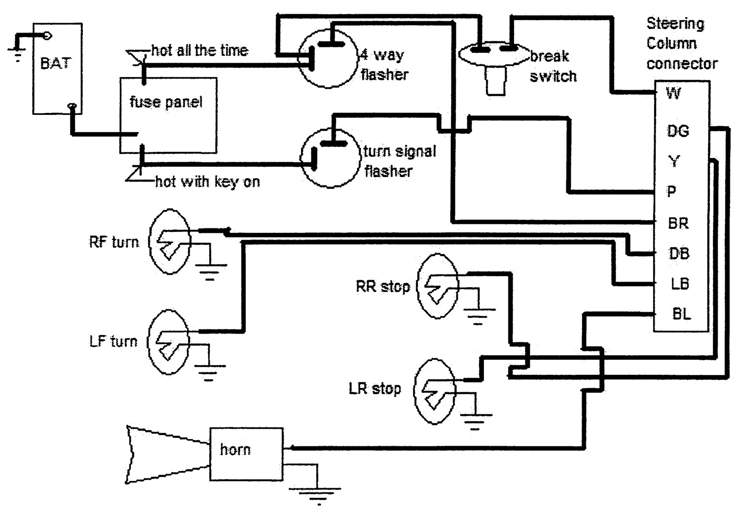
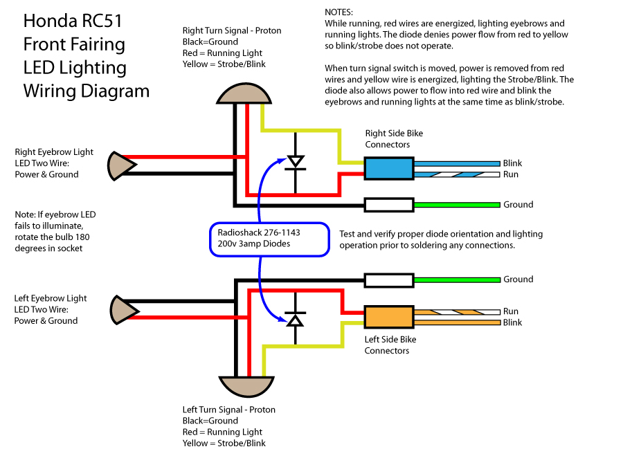
Turn signal wiring diagram. 23 identify the referencing the wiring diagram at the right, orangewire on the turn signal relay harness. 1 trick that we 2 to printing a similar wiring plan off twice. Left turn signal wiring diagram light blue (left front ts) yellow (left rear ts) green (right rear ts) 4 brown (hazards) not connected +12v, white (brake lts) always connected (controlled by brake pedal) +12v, purple (turn signal power) turn signal power (purple) connected to left side turn signals (light blue, yellow).
From there it goes to the stalk on the steering column. Make your own switch system. The other thing you will come across a circuit diagram could be traces.
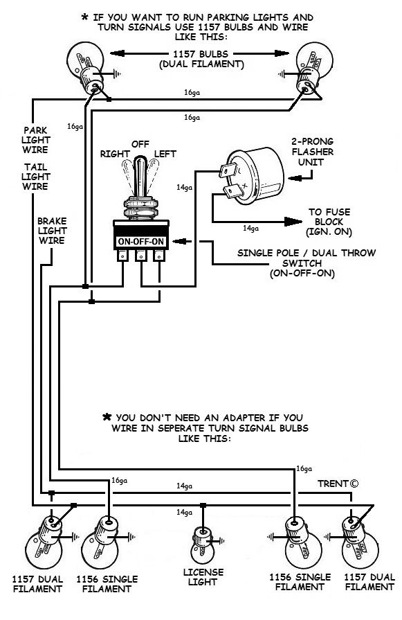
This lets me have turn signals that do not show yet they work well. • connect the turn signal adapter yellow wire, directly to the front left amber light lead wire on your car. The first element is symbol that indicate electrical component in the circuit.
Brake light turn signal wiring diagram wiring diagram is a simplified agreeable pictorial representation of an electrical circuit. Just remove the blue or orange jumper leads and connect your turn signal adapter leads. Externally, the only difference is in the connection for the dash indicator.
See * on wiring diagram. The relay is an electromagnetically operated switch, where with a low level input current, typically in the range of 100 ma and 150 ma, can be switched high level current up to 80 a, in some cases and more. It shows the parts of the circuit as simplified forms, and also the power and also signal links in between the devices.
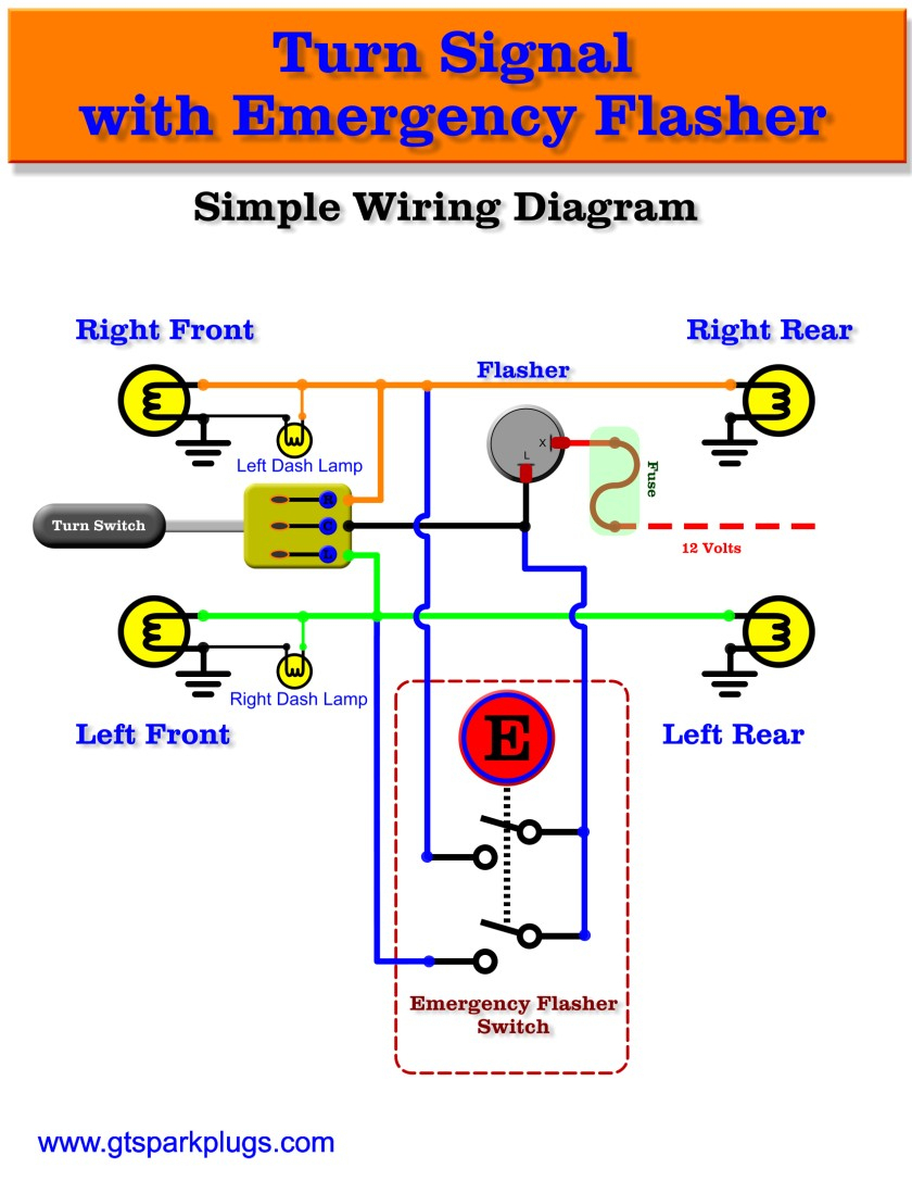
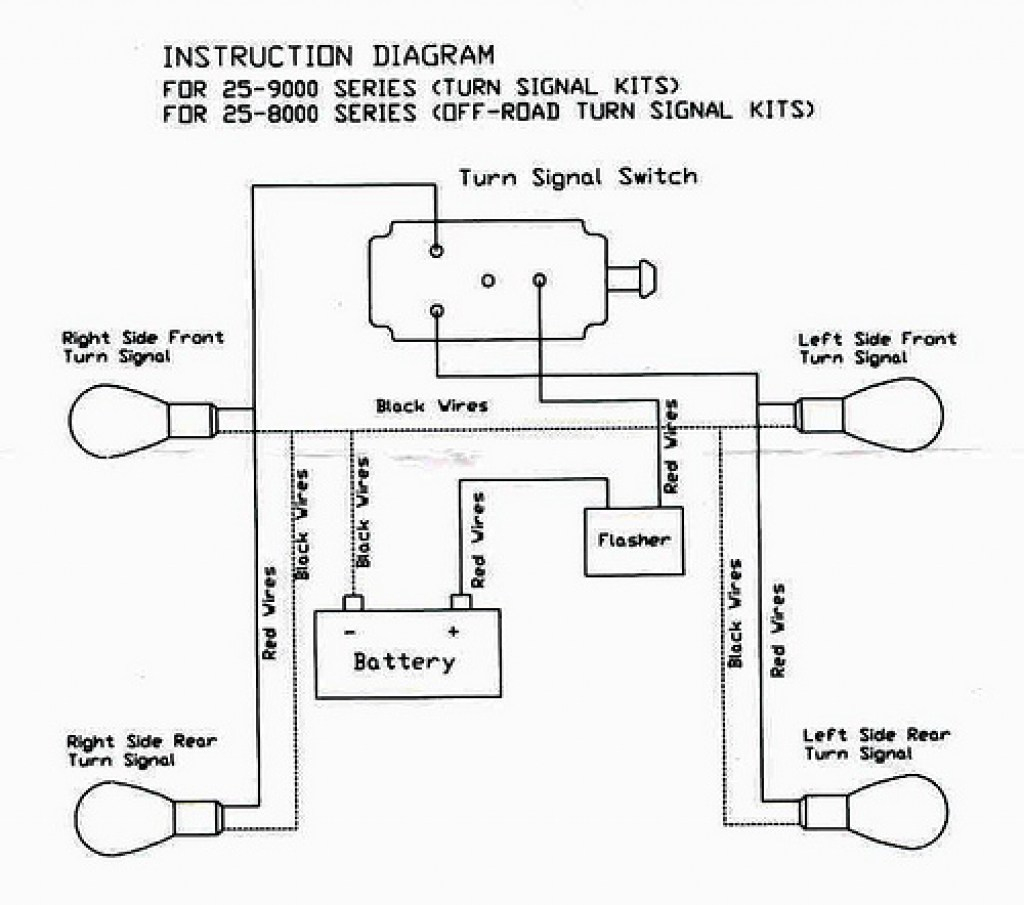
The following diagram shows the required wiring for this system. You will be in a position to understand exactly once the tasks needs to be finished, that makes it easier for you to properly control. This diagram shows the turn signal flasher circuit in its simplest form:
Heres the 82 pontiac rwd car shop manual wiring diagram for the turn signal switch. Wellborn variety of universal turn signal wiring diagram. This information covers the signal stat series 900 turn signals double click on any picture for full screen size turn signal wiring diagrams • public gallery • help
The flasher receives power from one of 2 fuses, depending on whether or not When the input current flows through the copper coil, the magnetic field is generated and the. Print the wiring diagram off plus use highlighters to trace the signal.
Motofix phsend me stuff?for sponsorship?business inquiries!email me: • connect the turn signal adapter green wire, directly to the front right amber light lead wire on your car. Want to add turn signals to your hotrod?
For instance , in case a module is powered up and it sends out the signal of half the voltage in addition to the technician will not know this, he'd think he offers a challenge, as he or she would. All youre worried about is the brake and turn signal. Turn signal switch with integral pilot lamps.
On my 1930 tudor i use the cowl lights for the front turn signals and use the stop light bulb in the rear. A circuit is generally composed by several components. The first component is symbol that indicate electrical component from the circuit.
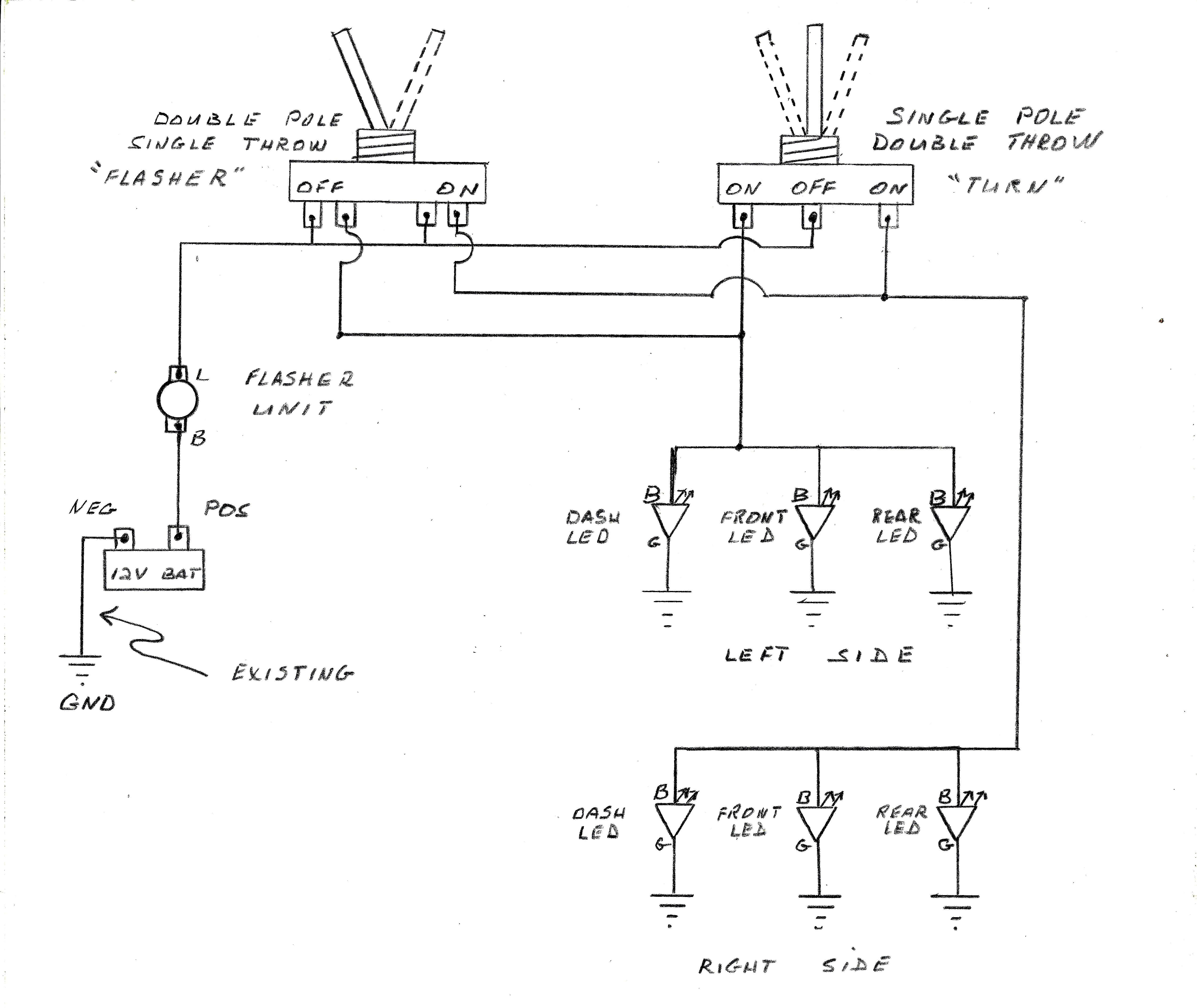
What you need to do is find the wiring. The one automotive job we all dread is the wiring. How to add turn signals and wire them up.
Comment & subcribe :)'do it at your own risk'follow me onfacebook: Draw a diagram to map out your wires and connections. Universal turn signal wiring diagram march 16, 2019 by larry a.
Basic turn signal wiring diagram basic turn signal wiring diagram. A wiring diagram is a streamlined standard pictorial depiction of an electric circuit. Insert the end of the red wire into the tap, then fold the cover over and press together.
When you make use of your finger or perhaps the actual circuit with your eyes, it is easy to mistrace the circuit. A circuit is usually composed by several components. Continuity diagram 3456 7 8 9 functions headl dimmer 2 stop rn turn turn turn ight rear.
There are just two things which are going to be found in any turn signal flasher wiring diagram. For me the easy way would be to just run a third light for my brake light. 65 mustang turn signal switch wiring diagram from averagejoerestoration.com.
Another thing that you will locate a circuit diagram would be traces. It includes instructions and diagrams for various kinds of wiring strategies and other things like lights, home windows, and so on. There are two things which are going to be present in almost any brake and turn signal wiring diagram.
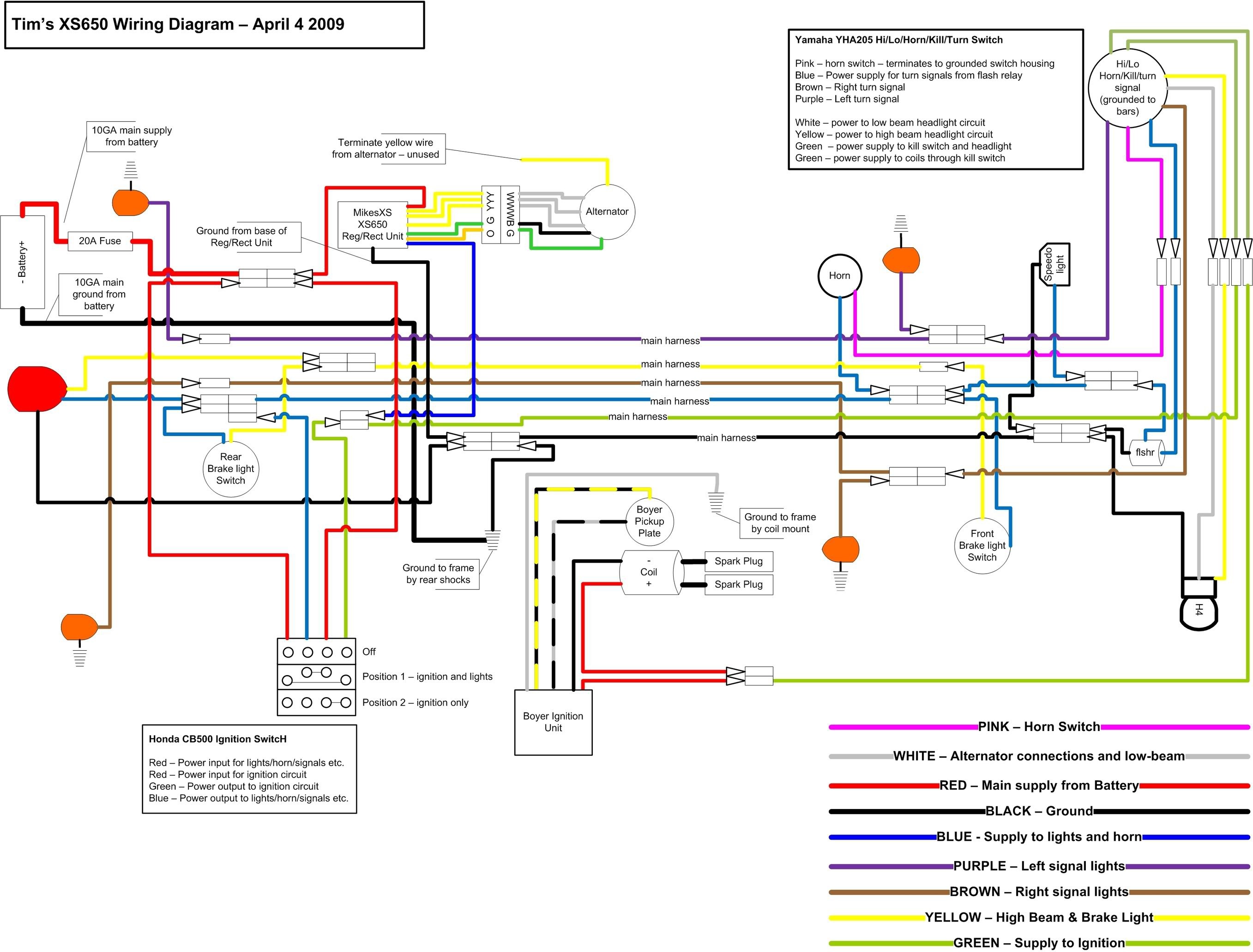
The power goes through a fuse panel into the thermal flasher. Gm turn signal switch wiring diagram from www.justanswer.com effectively read a cabling diagram, one has to find out how typically the components inside the method operate. The attached wiring diagram shows where each of the wires goes and its function.
(it's easy!) factory switchmost of you will have a hotrod that uses a steering column that has a turn signal switch built in.
How to Wire a Motorcycle (Basic Wiring Diagrams)

Turn Signal Flasher Wiring Diagram Wiring Diagram
Motorcycle Led Turn Signal Wiring Diagram Collection Wiring Diagram Sample

Grote Turn Signal Switch Wiring Diagram
Turn Signal Relay Wiring Wiring Diagram Image
TL1000R Front Turn Signal Wiring...

Customs need help wiring an add on turn signal switch The H.A.M.B.
Universal Turn Signal Wiring Diagram Cadician's Blog
Universal Turn Signal Switch Wiring Diagram Cadician's Blog
Utv Turn Signal Wiring Diagram Collection Wiring Diagram Sample

Cavalier Turn Signal Wiring Diagram Wiring Diagram
Projects Aftermarket signal switch KD728 help The H.A.M.B.
Gm Turn Signal Wiring Diagram
Tj turn signal wiring diagram
Turn Signal Troubleshooting Speedzilla Motorcycle Message Forums
Universal Turn Signal Switch Wiring Diagram Wiring Diagram And Schematic Diagram Images

Turn Signal Relay Wiring Diagram Wiring Diagram And Schematic Diagram Images

The Care and Feeding of Ponies 1965 1966 Mustang Turn signal switch wiring

How to Add Turn Signals and Wire Them Up